| Prev | Next |
Boundary
Getting to know the Boundary
Aspect |
Description |
|---|---|
|
Introducing the Boundary |
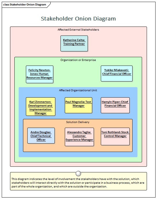
The Boundary element is derived from the Use Case system boundary but can be used extensively in other contexts as a way of describing a separation between a system or part of a system and its external environment. Any number of Boundaries can be added to a diagram and other elements such as Use Cases, Features, Requirements, Components and more can be placed inside the boundary. The properties of the Boundary can be altered to show a number of compartments organized into vertical and horizontal swimlanes. The border style and opacity of the Boundary can also be set.
|
|
Where to find the Boundary |
UML Elements Toolbar | Boundary Common Toolbox Page | Boundary |
|
Usage of the Boundary |
The Boundary element is particularly useful for defining what is inside a system (or part of a system) and what is outside. It can be used to show the Use Cases of a system or subsystem, the in-scope Features or Requirements. Diagrams created for management and non-technical audiences will benefit from the use of Boundaries, which can be colored and nested to have visual appeal and business meaning. It is essentially a diagrammatic device and does not appear in the Project Browser. If a formal and structural grouping of elements is needed, the modeler could consider the use of a Package. |
|
Options for the Boundary |
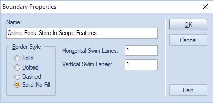
The Boundary can be configured to have a number of vertical and horizontal swimlanes, which are useful for grouping elements into different sections of the boundary, creating a matrix effect. The Border Style can also be configured to allow different line styles that can then be colored using the standard element appearance settings. Also, choosing the 'Solid' options allows the Boundary's fill color to be set.
|
|
Learn more about the Boundary |