| Prev | Next |
Flow Chart
A Flow Chart is a graphical representation of a sequence of events, helping decision makers understand the relationship between their decisions and a given outcome. Flow Charts use a range of simple geometric shapes to represent a process, decision, storage or output.

Creating a Flow Chart
Create a flowchart for hiring staff at a Restaurant.
- Create a new Package called 'Flow Chart'. Add a Flow Chart diagram from the Strategic Modeling category.
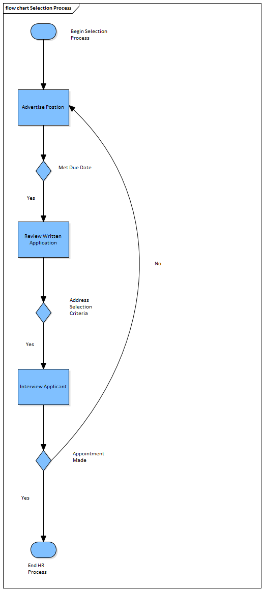
- Place a 'Begin' and 'End' icon onto the diagram. Name the two respective items 'Begin Selection Process' and 'End HR Process'.
- Create two different Processes called 'Advertise Position' and 'Review Written Application'.
- Create a Decision called 'Met Due Date'. This decision will be used to determine if a candidate will proceed to the written application stage.
- Draw a connector between 'Begin Selection Process' and 'Advertise Position' followed by another connector between 'Advertise Position' and 'Met Due Date'.
- Right-click on the Connector located between 'Advertise Position' and 'Met Due Date' and select the ControlFlow properties. Name the Connector 'Yes'. By labeling the Connector with the word 'Yes' we assert that if an application is received by the due date then it will be reviewed by staff in the Human Resources department. Any submissions received after the due date will not be reviewed by staff.
- Create a Decision called 'Address Selection Criteria'. Draw a Connector from 'Review Written Application' to the Decision 'Address Selection Criteria'.
- Create a Process called Interview Applicant'. Draw a Connector from 'Address Selection Criteria' to 'Interview Applicant' and label the Connector 'Yes' denoting that if the applicant has addressed the selection criteria then proceed to 'Interview Applicant'.
- Create a Decision called 'Appointment Made'. For the 'Yes' response, draw a Connector to 'End HR Process'.
- For the 'No' response, draw a connector to 'Advertise Position'. Note: you could use a Bezier Connector (a curved line) to improve the diagram layout.
- Select the entire diagram () and select 'Align Centers | Align Vertically'.