| Prev | Next |
Signal Events
A Signal Event provides the facility of loosely coupling 'throwers' and 'catchers' by publish-subscribe integration. A 'thrower' will broadcast a signal rather than addressing it to a particular process; any process listening for that particular event could trigger a new instance using a Signal Start Event.
A Signal can be thrown from either a throwing Intermediate Event or a throwing End Event, and can be caught in a Start Event or a catching Intermediate Event (including a boundary Signal Event).
In this example, we demonstrate these Signal Events and their impact on the lifelines of tasks, via BPSim parameter settings.
- Start Signal Event:
- Start By Signal1 in top level process (Pool1)
- Start By Signal2 Interrupting in event sub-process eventSubProcess2
- Start By Signal1 Non Interrupting in event sub-process eventSubprocess1
- Throwing Intermediate Signal Event:
- Broadcast Signal1
- Catching Intermediate Signal Event:
- Receive Signal1 (normal)
- Receive Signal2 (normal)
- Receive Signal2 (boundary Interrupting)
- Receive Signal1 (boundary non-interrupting)
- Receive Signal2 (in Event Gateway)
- End Signal Event:
- End By Throwing Signal2
Create BPMN Model
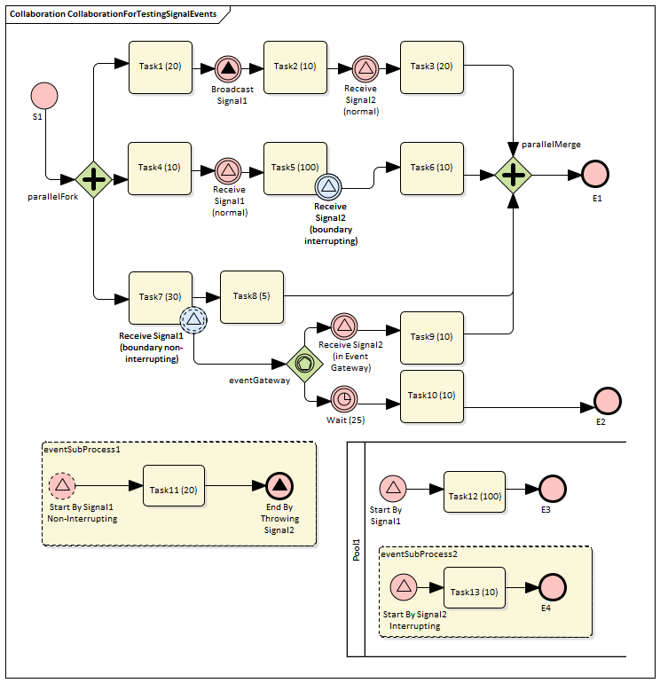
In order to demonstrate the ability to communicate across processes via a Signal Event, we create a Collaboration model with a main Pool and a process in another Pool (Pool1).
Create the Collaboration and main process
Create a new BPMN2.0 Collaboration diagram called CollaborationForTestingSignalEvents, (choose the option 'Create this diagram within a new Collaboration Model'). Right-click on the diagram name in the Project Browser and select the 'Encapsulate Process' option.
A Pool PoolMain and a process BusinessProcess_PoolMain are created, and these tags are set with the automatic values:
- CollaborationForTestingSignalEvents.mainPool is set to PoolMain
- PoolMain.processRef is set to BusinessProcess_PoolMain
Create the elements for the main process
Create a Start Event S1 and add a Sequence Flow to a Fork Parallel Gateway parallelFork
Add Sequence Flows to:
- An Abstract Task Task1 (20) and then add this chain of Sequence Flows:
- To a Throwing Intermediate Signal Event Broadcast Signal1
- Then to an Abstract Task Task2 (10)
- Then to a Catching Intermediate Signal Event Receive Signal2 (normal)
- Then to an Abstract Task Task3 (20)
- Then to a Merge Parallel Gateway parallelMerge
- Then to an End Event E1
- An Abstract Task Task4 (10) and then add this chain of Sequence Flows:
- To a Catching Intermediate Signal Event Receive Signal1 (normal)
- Then to an Abstract Task Task5 (100), on which you create a Boundary Interrupting Catching
Intermediate Signal Event Receive Signal2 (boundary interrupting)
- Then to an Abstract Task Task6 (10)
- Then to the earlier Merge Parallel Gateway parallelMerge
- An Abstract Task Task7 (30), and then add this chain of Sequence Flows:
- To an Abstract Task Task8 (5)
- Then to the earlier Merge Parallel Gateway parallelMerge
On Task7 (30), create a Boundary Non-interrupting Catching Intermediate Signal Event Receive Signal1 (boundary non-interrupting). Add a Sequence Flow to an Event Gateway eventGateway, and to that add Sequence Flows to:
- A Catching Intermediate Signal Event Receive Signal2 (in Event Gateway), and then this chain of Sequence Flows:
- To an Abstract Task Task9 (10)
- Then to the earlier Merge Parallel Gateway parallelMerge
- A Catching Intermediate Timer Event Wait (25), and then this chain of Sequence Flows:
- To an Abstract Task Task10 (10)
- Then to an End Event E2
Create an Event sub-process (triggered by a non-interrupting Start Signal Event) in the main process
- Create an Activity eventSubProcess1 and, in its 'Properties' dialog, set the 'Type' field to subProcess and change the attribute 'triggeredByEvent' to true
- Within eventSubProcess1 create a Start Event Start By Signal1 Non Interrupting and, in its 'Properties' dialog, set the 'Type' field to Event Sub-Process Non-Interrupting > Signal
- Add a Sequence Flow to a target Abstract Task Task11 (20)
- Add a Sequence Flow to a target End Event End By Throwing Signal2 and, in the element 'Properties' dialog, set the 'Type' field to Signal
Create another process
- From the Toolbox, drag and drop the 'Pool' icon onto the diagram and name the element Pool1
- Right-click on Pool1 in the Project Browser and select the 'Encapsulate Process' option; a process BusinessProcess_Pool1 is created and the tag 'Pool1.processRef' is set to BusinessProcess_Pool1
Create the main process for Pool1
- Create a Signal Start Event Start By Signal1
- Add a Sequence Flow to a target Abstract Task Task12 (100)
- Add a Sequence Flow to a target End Event E3
Create an Event sub-process to interrupt Pool1
- Create an Activity eventSubProcess1 and, in the 'Properties' dialog, set the 'Type' field to subProcess; change the attribute 'triggeredByEvent' to true
- Within eventSubProcess2 create a Start Event Start By Signal2 Interrupting and, in the 'Properties' dialog, set the 'Type' field to Event Sub-Process Interrupting > Signal
- Add a Sequence Flow to a target Abstract Task Task13 (10)
- Add a Sequence Flow to a target End Event E4
Create the BPMN2.0 Signal Elements and configure for Signal Events
In the BPMN 2.0 Toolbox, expand the 'BPMN 2.0 - Types' page and drag the 'Signal' icon onto the diagram; name the element Signal1. Drag the icon onto the diagram again to create Signal2. These are root elements (which can be used by all processes) so they will be created directly under the model Package.
Double-click on each of the Signal Event elements and, in the 'Value' field for the 'signalRef' tag, click on the  button and browse to the appropriate Signal element.
Tips: Alternatively, you can drag the Signal element from the Project Browser and drop it on the Event elements in the diagram; a context menu displays, from which you select the 'set signalRef' option.
- Set signalRef to 'Signal1' on:
- Broadcast Signal1
- Start By Signal1 in top level process (Pool1)
- Start By Signal1 Non Interrupting in Event sub-process eventSubprocess1
- Receive Signal1 (normal)
- Receive Signal1 (boundary non-interrupting)
- Set signalRef to 'Signal2' on:
- Start By Signal2 Interrupting in Event sub-process eventSubProcess2
- Receive Signal2 (normal)
- Receive Signal2 (boundary Interrupting)
- Receive Signal2 (in Event Gateway)
Configure BPSim
In this section, we create the Configuration Artifact, specify the model Package and configure the parameter values of each element.
The configuration is quite simple because none of the Signal Events require any BPSim configurations. All we have to do is set the processing time for tasks so we can observe how processes, threads and tasks are started and interrupted.
Task |
Description |
|---|---|
|
Set up configuration |
Then all the BPMN elements will be loaded in to the Configure BPSim window. |
|
Non-Signal Events |
|
|
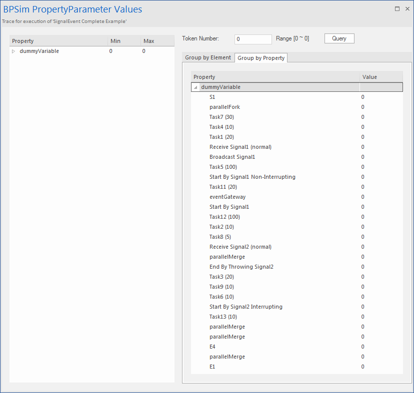
Dummy variable for Process |
The simulation controller displays a list showing the runtime token count for each element. For example, 4 tokens have passed the Gateway element parallelMerge in a simulation. This is quite useful for certain statistics and analysis. However, it does not show WHEN parallelMerge was traversed during the simulation. In order to get the exact trace for a single token we use the property trace utility, which relies on property parameters. So we create a dummy parameter. In the 'Configuration BPSim' dialog, expand the 'BusinessProcess' group.
|
|
Processing Time for Tasks |
Expand the 'Activity' group and for each Task element listed here: select the 'Time' tab, click on the 'New Parameter' drop-down arrow and select 'ProcessingTime', then click on the
|
Run Simulation
 button on the tool bar to display the 'BPSim PropertyParameter Values' dialog
Analysis
From the direct results of the simulation it might not be obvious what has taken place; however, if we draw the lifeline for each task, it becomes quite clear.
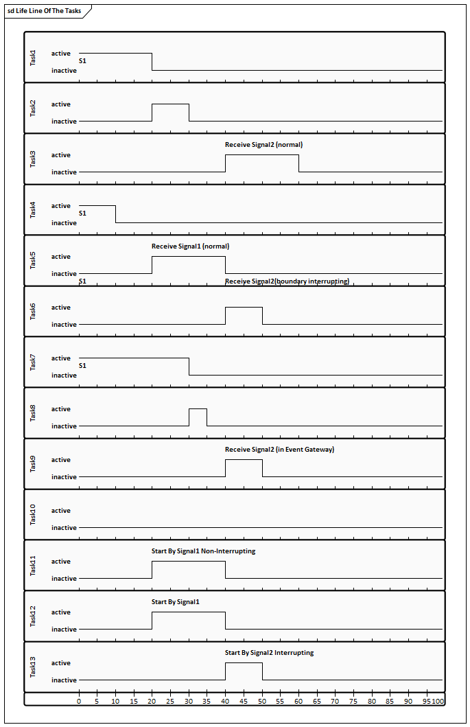
- Task1, Task4 and Task7 started in parallel
- Task2 started immediately after Task1 finished (without stopping at the throwing event)
- At 20 seconds, Signal1 was broadcast by the Throwing Intermediate Event Broadcast Signal1 and:
- Receive Signal1 (normal) was activated and Task5 started
- Start By Signal1 Non-Interrupting was activated and Task11 in eventSubProcess1 started
- Start By Signal1 was activated and Task12 in Pool1 started
- At 40 seconds, Signal2 was broadcast by the End Event End By Throwing Signal2 and:
- Receive Signal2 (normal) was activated and Task3 started
- Task5 was interrupted and Task6 started
- Receive Signal2 (in Event Gateway) was activated and Task9 started
- Start By Signal2 Interrupting was activated, and:
> The main process in Pool1 was interrupted and Task12 stopped
> Task13 in eventSubProcess2 started
- The eventSubProcess2 inside BusinessProcess_Pool1 finished when E4 was reached at 50 seconds
- The BusinessProcess_MainPool finished when E1 was reached at 60 seconds
- The Intermediate Timer Event Wait (25) did not get activated because the signal event in the Gateway was activated first; as a result, Task10 was never started
Note: The actual running time for each task can be observed from the generated BPSimReport element, by:
- Double-clicking on the <<BPSimReport>> element.
- Expanding the 'Time' group.
- Expanding the task element.
- Checking 'Total Time In Task'.
For example, for element Task5 (100), although we set its processingTime to be 100 seconds, the Total Time In Task was 20 seconds, which was interrupted by Receive Signal2 (boundary interrupting) at 20 seconds.

