| Prev | Next |
SysML Model Elements Toolbox
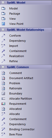
When you are constructing SysML models, you can populate the diagrams with Model, Package and View elements using the icons on the 'SysML Model' pages of the Diagram Toolbox.
The SysML Model toolbox includes a page of SysML Common element and relationship icons. You can add this page to all Diagram Toolboxes so that it is always available regardless of what type of diagram you are using; to do this, set the SysML 1.5 Technology to 'Active' ('Specialize > Technologies > Manage : SysML 1.5 : Set Active' ribbon path).

Access
On the Diagram Toolbox, click on  to display the 'Find Toolbox Item' dialog and specify 'SysML n.n Model Elements' (whichever version you are using).
|
Ribbon |
Design > Diagram > Toolbox |
|
Keyboard Shortcuts |
|
SysML Model Element Objects
Item |
Description |
|---|---|
|
Model |
Creates a Package containing a SysML Model. |
|
Model Library |
Creates a Package containing a SysML Model Library. |
|
View |
Creates a stereotyped Class that defines a SysML View of a system, from the perspective of a SysML View Point. |
|
View Point |
Creates a stereotyped Class that defines a SysML View Point, which specifies the rules and conventions for the construction and use of Views. |
|
Stakeholder |
Creates a stereotyped Class that defines a SysML Stakeholder. |
|
Package |
Groups model constructs in a single unit of containment. |
SysML Model Relationships
Item |
Description |
|---|---|
|
Conform |
Establishes a conformance dependency of a View to the defining View Point. |
|
Dependency |
Establishes a traceable relationship describing how one element is dependant upon another. |
|
Import |
Represents a reuse of elements from one model Package in another. |
|
Containment |
Graphically displays ownership of one element within a parent one. |
|
Realization |
Identifies a design fulfillment of a specification between elements. |
|
Refine |
Represents a refinement of one element by another. |
|
Expose |
Relates a View to another model element. |
SysML Common
Item |
Description |
|---|---|
|
Comment |
Creates a textual annotation that can be attached to a set of elements of any other type. The attachment is created separately, using a Notelink connector. |
|
Document Artifact |
Attaches a linked document to the diagram by associating this element with the document. |
|
Element Group |
Creates a textual annotation that indicates how many model elements it is attached to. |
|
Problem |
A stereotyped Comment that documents the failure of model elements to satisfy a requirement. |
|
Rationale |
A stereotyped Comment that documents the justification for decisions. |
|
Boundary |
Defines a conceptual boundary, to visually group logically related elements. |
|
Allocate Partition |
A stereotyped Activity Partition that contains elements deemed to be allocated to the classifier of the partition. |
|
Requirement |
Specifies the capabilities of the system, or the conditions that it should satisfy. |
|
Allocated |
A stereotyped Comment that defines the source element being allocated to the target element in an Allocate relationship. |
|
Allocate |
A stereotyped Abstraction that relates model elements to formalize a refinement of behavior, structure, constraints or design expectations. The Allocate relationship points from the element being allocated to the element that is the target of the allocation. The system provides an 'Allocations' search that lists all Allocate abstractions in tabular format, showing the 'To' and 'From' elements. Select the 'Start > Explore > Search > Model' ribbon option, then select 'SysML 1.4' as the Search Category; 'Allocations' defaults as the Search Type. If a SysML Block element has any Allocate relationships to or from elements that are not visible on the same diagram, those elements can be listed in 'AllocatedTo' and 'AllocatedFrom' compartments of the Block element on the diagram. Press to display the 'Compartment Visibility' dialog and select the 'Allocatedto' and/or 'Allocatedfrom' checkboxes. Alternatively, you can list the hidden elements on a linked Note. Create a Note element on the diagram and link it to the visible Block element with a Notelink connector. Right-click on the connector, select the 'Link this Note to an Element feature' option and, on the 'Link note to element feature' dialog, click on the drop-down arrow on the 'Feature Type' field and select 'AllocatedTo' or 'AllocatedFrom'. Click on the ; the names of the linked elements are now displayed in the Notes element. (To show both 'To' and 'From' elements, create a separate Note for each type.) For either compartments or Notes, you should save the diagram just before setting up the facility, and possibly reload the diagram to activate the facility. If there are no Allocate relationships, or the related elements are on the diagram, the options are not available. |
|
Containment |
Graphically displays ownership of one element within a parent one. |
|
Dependency |
Establishes a traceable relationship describing how one element is dependant upon another. |
|
Binding Connector |
A stereotyped Connector that establishes a connection between two parts in a system decomposition. |
|
Item Flow |
A stereotyped Information Flow that specifies the items that flow across a connector in an interaction point. |

