| Prev | Next |
Model Requirements
Requirements are fundamental to the success of any project, regardless of the process being used. Many organizations have traditionally stored and managed their requirements in text tools like spreadsheets and word processors; these requirements often remain hidden from the development process. Using Enterprise Architect’s model based approach to requirements engineering turns requirements into first class modeling elements. They can be displayed on diagrams and related to the stakeholders that own them, and traces can be created connecting them to other down-process model elements such as Use Cases and application Components.
Properties such as status, phase, complexity and difficulty can be assigned to each requirement, which helps you to manage them easily.
Features
Feature |
Detail |
See also |
|---|---|---|
|
Represent Requirements |
In Enterprise Architect, a requirement can be modeled as an:
Requirements Management in Enterprise Architect is primarily concerned with Requirement elements and the elements that implement or realize them. |
Requirements Internal requirements |
|
Requirements in the Model |
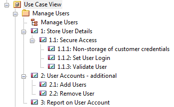
Requirement elements can be grouped and organized within Requirements diagrams. The Requirement elements are connected to each other by Aggregate relationships to form a hierarchy:
It is quite usual to develop a Package of many hundreds of Requirement elements, arranged individually and in hierarchies of varying complexity. You can select a Package and use the 'Design > Package > Edit > Advanced > Toggle Level Numbering' ribbon option to highlight the order and arrangement of the Requirements quickly and easily. This illustration shows a number of Requirements in a Package, where Level Numbering makes the order and arrangement clear:
If elements are added, moved or deleted from the Package, the numbering automatically adjusts. This numbering can also be applied in a document. |
Requirements Diagram Turn On Level Numbering Design Custom Document Templates |
|
Use Cases |
Requirements are implemented (realized) by model elements such as Use Cases, Classes, Interfaces and Components. There are many ways to trace either the Requirement for the feature or service modeled by the elements, or the elements that develop the requirement, most visibly in Traceability diagrams that depict the Requirements and the model elements connected by Realize relationships. The Realize connector enables members of the project team to keep design objectives and development in tandem, and the development path and purpose clear.
The more usual realization relationship is between a Requirement and a Use Case. A Requirement can be realized by one or more Use Cases, and a Use Case can realize one or more Requirements. Whilst a Requirement defines a condition that must be met, the Use Case is the key to defining and visualizing how that condition is met. A Use Case diagram depicts the logical grouping of actions, processes and components to achieve a required result, and through the use of Actor elements also defines the user and/or system roles participating in the process. Each Use Case (as a composite element) can contain a combination of child diagrams that define in greater detail how a particular activity or facility might be implemented - such diagrams include Sequence, Communication, Activity, StateMachine and Business Rule Flow diagrams. The actual implementation of each Use Case is realized by Class, Component and Interface elements organized in their own diagrams. These realizations can also be captured and viewed in Traceability diagrams, depicting the full development pathway from initial requirement through to testing and production. |
Trace: Tracking Dependencies Example Traceability Diagram Connector Requirement Use Case Use Case Diagram Actor Composite Element Sequence Diagram Communication Diagram Activity Diagram State Machine Diagram Create a Rule Flow Activity |