| Prev | Next |
Composite Elements
You might want to use one element to represent a structure composed of other elements; for example, a general Use Case representing a collection of more specific Use Cases. To achieve this, you can make the 'general' element a composite element, as a pointer to a child diagram containing the 'detail' elements. The elements that you can turn into composites include Classes, Objects, Activities and Use Cases.
Access
|
Ribbon |
With an element selected in the Project Browser: Design > Diagram > Insert : Select From > Software Construction | UML | UML Structural | Composite Structure | <one of the two diagram types> There are several Perspective groups and Perspectives that lead you to the UML Structural group; the one provided is an example. |
|
Context Menu |
Right-click element in diagram | New Child Diagram | Composite Structure Diagram or Right-click element in Project Browser | Add | Composite Structure Diagram |
Make an element composite
Images |
Step / Action |
See also |
|---|---|---|

|
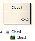
When you select to make an element composite, it displays in the diagram and in the Project Browser as illustrated on the left. Note:
|
|

|
Double-click on the composite element in the diagram to access the child diagram that it points to. You can populate the child diagram with elements and connectors to represent the internal structure of the (parent) composite element. In this process, structural (embedded) elements cannot be directly added to the child diagram. However, you can add them using a different, modified procedure. The composite element and its child diagram are now represented in the Project Browser as shown. ClassX, ClassY and ClassZ are elements added to the child diagram. |
Show Structural Elements In Composite Diagram |

|
If you already have, or subsequently create, another diagram that better represents the content of your composite element, you can select that diagram as the child of the composite. Right-click on the composite element in its diagram and select the 'New Child Diagram | Select Composite Diagram' option. The 'Select Classifier' browser displays, through which you can browse the entire project to locate the alternative diagram. Click on the diagram and on the to apply it as the child of the composite element. Neither the original nor the alternative child diagram move location or change icons in the Project Browser (unless you specifically make these changes as a separate operation). |
Alternative Notation
You can display the contents (the child diagram) of a Composite element within the element, in two ways.
Display Format |
Detail |
See also |
|---|---|---|
|
Display Composite Element as Frame 
|
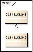
Composite elements can show their contents in place of their usual notation.
The composite element is replaced by a frame containing the child diagram. The frame label shows the composite element name. The element is resized to contain the diagram; whilst it can be enlarged, it cannot be reduced to less than the diagram size. Some technologies, such as SysML, qualify the frame label to show the diagram type, element type, element name and child diagram name. If you design custom diagram profiles, you can also qualify the frame label as required. |
Create Custom Diagram Profiles |
|
Display Composite Element Content In Compartment 
|
Composite elements can also show their contents in addition to their usual notation, in a separate compartment of the element.
A compartment is added to the element, containing the child diagram. The element is resized to contain the diagram; whilst it can be enlarged, it cannot be reduced to less than the diagram size. You can also display a Composite diagram inside its parent element using a Shape Script. The diagram is displayed in a custom compartment in the center of the element and not necessarily with the standard compartments (such as attributes, tags). |
Show Composite Diagram |
Notes
Learn more

