| Prev | Next |
Scope Modeling
Enterprise Architect has a number of facilities that can be used to model scope, depending on the type of depiction required. The most simple is the use of a Boundary element to separate elements that are part of the scope - inside the Boundary - and those that are not part of the scope - outside the boundary. The Boundary element is also formally part of the Unified Modeling Language (UML) and can be used to define a system boundary as part of a Use Case diagram, where the Use Cases lie inside the Boundary and the Actors lie outside. Scope can also be modeled using Features, which are used to define conditions a system must have and which are typically arranged hierarchically. The Features can be defined in the Project Browser and also displayed on a Requirements diagram.

Project Browser
A Feature hierarchy can be created using the Project Browser without the need to create a diagram. A system Feature is a good way to capture the high level capabilities of a system; these can be created directly in the Project Browser. Additional Features can be added under each first level Feature creating a second level of features. These second level Features can have Features nested under them creating a third level. The resulting tree of Features provides a useful way of describing system scope that can be presented to and reviewed by stakeholders. It is sometimes useful to list out-of-scope Features - a separate Package could be created in the Project Browser to contain these.
Learn More: Project Browser
Requirements Diagram
Requirements diagrams can be used to create a hierarchy of system Features. A system Feature is a good way to capture the high level capabilities of a system, which can be broken down to a number of levels using a tree structure using an Aggregation or Composition Relationship. This provides a compelling representation of scope that can be reviewed by the stakeholders and used as a guide through the initiative. Gaps and out-of-scope Features should be identified as early as possible and the tree amended to reflect these. Out of Scope Features could be left as part of the tree but annotated in some way to indicate that they are out of scope such as by using a stereotype or by using color with a Diagram Legend.
As an alternative representation, Features could also be nested inside each other in the diagram down to a number of levels. This method has the advantage that the Features will be automatically nested underneath each other as child elements in the Project Browser.
Learn More: Requirements Diagram
Scope Boundary
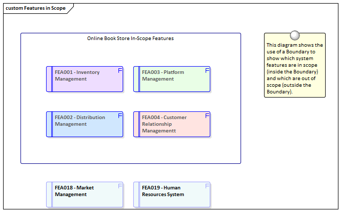
Enterprise Architect has a convenient and flexible Boundary element that can be used to represent the boundary of a system. It is a rectangular element that can be resized and styled to suit the elements that are in scope and will thus reside inside the Boundary. Out-of-scope elements could be placed outside the boundary to ensure that stakeholders are clear about what is in and out of scope. The elements placed inside the boundary could be Requirements, Features, Components or any other element type that would help indicate scope.
Learn More: Boundary
Use Case Diagrams
A Use Case diagram provides a convenient way of describing the scope of a System (or Entity). A System Boundary is used to mark the extent of the system; Actors (humans or systems that gain value from the system) are positioned outside the Boundary, and Use Cases (the goals the Actors intend to achieve) are positioned inside the Boundary. It is not necessary to complete the detailed steps of the Use Cases, but the Scenarios should be described to a level that will assist stakeholders in understanding the scope of the system.
Learn More: Use Case Diagram
User Stories
User Stories provide a useful way of describing the goals that users are trying to achieve. These are written from the users' perspective and typically describe things they need to achieve as part of their role. Collectively they provide a high level definition of the scope of the system or initiative. While the User Stories are not typically analyzed until close to implementation their high level descriptions provide a way of planning and determining what will be implemented as part of an iteration.
Learn More: User Stories

