| Prev | Next |
Water Tank Pressure Regulator
In this section we will walk through the creation of a SysML parametric model for a Water Tank Pressure Regulator, composed of two connected tanks, a source of water and two controllers, each of which monitors the water level and controls the valve to regulate the system.
We will explain the SysML model, create it and set up the SysMLSim Configurations. We will then run the simulation with OpenModelica.
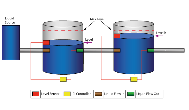
System being modeled
This diagram depicts two tanks connected together, and a water source that fills the first tank. Each tank has a proportional–integral (PI) continuous controller connected to it, which regulates the level of water contained in the tanks at a reference level. While the source fills the first tank with water the PI continuous controller regulates the outflow from the tank depending on its actual level. Water from the first tank flows into the second tank, which the PI continuous controller also tries to regulate. This is a natural and non domain-specific physical problem.
Create SysML Model
Component |
Discussion |
|---|---|
|
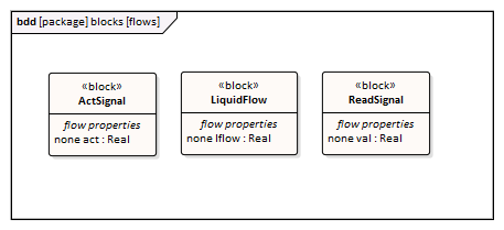
Port Types |
The tank has four ports; they are typed to these three blocks:
|
|
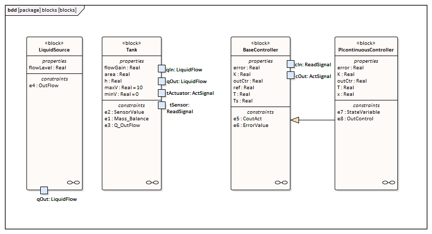
Block Definition Diagram |
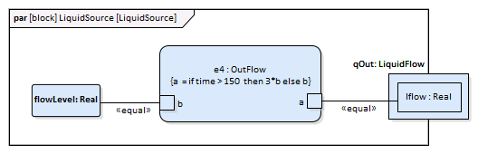
LiquidSource - The water entering the tank must come from somewhere, therefore we have a liquid source component in the tank system, with the property flowLevel having a unit of 'm3/s'. A Port 'qOut' is typed to 'LiquidFlow'. Tank - The tanks are connected to controllers and liquid sources through Ports.
BaseController - This Block could be super of a PI Continuous Controller and PI Discrete Controller.
PIcontinuousController - generalize from BaseController
|
|
Constraint Blocks |
The flow increases sharply at time=150 to a factor of three of the previous flow level, which creates an interesting control problem that the controller of the tank has to handle.
The central equation regulating the behavior of the tank is the mass balance equation. The output flow is related to the valve position by a 'flowGain' parameter. The sensor simply reads the level of the tank.
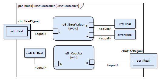
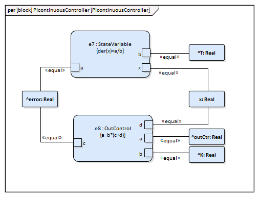
The Constraints defined for 'BaseController' and 'PIcontinuousController' are illustrated in these figures.
|
|
Internal Block Diagram |
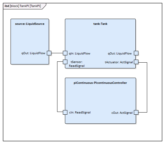
This is the Internal Block diagram for a system with a single tank.
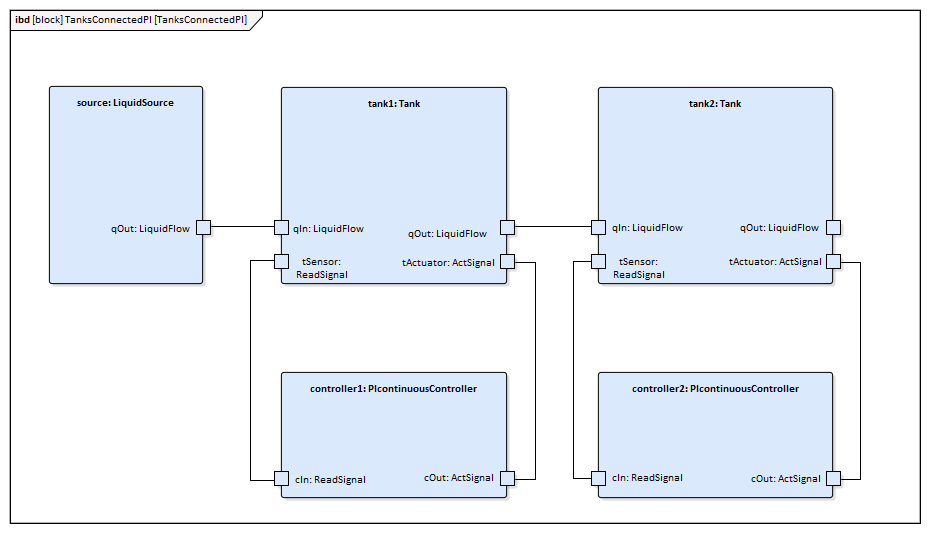
This is the Internal Block diagram for a system with two connected tanks.
|

Run Simulation
Since TankPI and TanksConnectedPI are defined as 'SysMLSimModel', they will be filled in the combo box of 'Model' on the 'Simulation' page.
Select TanksConnectedPI, and observe these GUI changes happening:
- 'Data Set' combobox: will be filled with all the data sets defined in TanksConnectedPI
- 'Dependencies' list: will automatically collect all the Blocks, Constraints, SimFunctions and ValueTypes directly or indirectly referenced by TanksConnectedPI (these elements will be generated as Modelica code)
- 'Properties to Plot': a long list of 'leaf' variable properties (that is, they don't have properties) will be collected; you can choose one or multiple to simulate, and they will become legends of the plot
Create Artifact and Configure
Select 'Simulate > SysMLSim > Manage > SysMLSim Configuration Manager'
The elements in the Package will be loaded into the Configuration Manager.
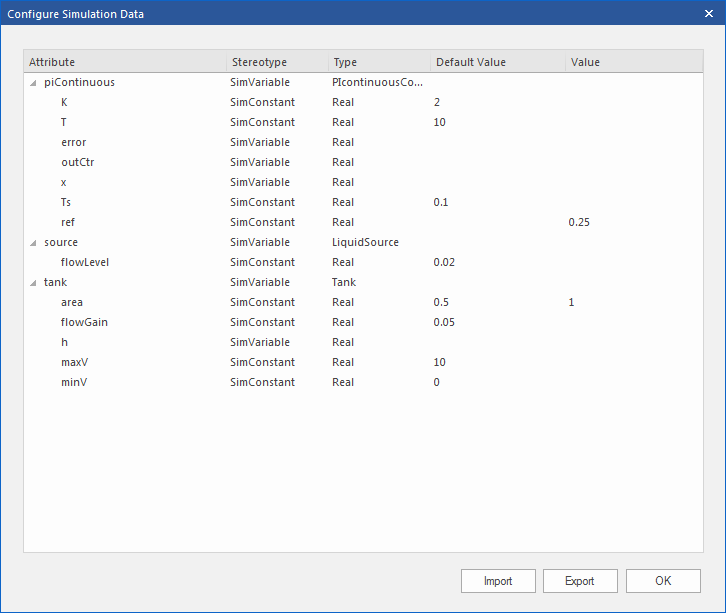
Configure these Blocks and their properties as shown in this table.
Note: Properties not configured as 'SimConstant' are 'SimVariable' by default.
Block |
Properties |
|---|---|
|
LiquidSource |
Configure as 'SysMLSimClass'.
Properties configuration:
|
|
Tank |
Configure as 'SysMLSimClass'.
Properties configuration:
|
|
BaseController |
Configure as 'SysMLSimClass'.
Properties configuration:
|
|
PIcontinuousController |
Configure as 'SysMLSimClass'. |
|
TankPI |
Configure as 'SysMLSimModel'. |
|
TanksConnectedPI |
Configure as 'SysMLSimModel'. |
Setup DataSet
Right-click on each element, select the 'Create Simulation Dataset' option, and configure the datasets as shown in this table.
Element |
Dataset |
|---|---|
|
LiquidSource |
flowLevel: 0.02 |
|
Tank |
h.start: 0 flowGain: 0.05 area: 0.5 maxV: 10 minV: 0 |
|
BaseController |
T: 10 K: 2 Ts: 0.1 |
|
PIcontinuousController |
No configuration needed.
By default, the specific block will use the configured values from super block's default dataSet. |
|
TankPI |
What is interesting here is that the default value could be loaded in the 'Configure Simulation Data' dialog. For example, the values we configured as the default dataSet on each Block element were loaded as default values for the properties of TankPI. Click the icon on each row to expand the property's internal structures to arbitrary depth.
Click on the and return to the Configuration Manager. Then these values are configured:
|
|
TanksConnectedPI |
|
Simulation and Analysis 1
Select these variables and click on the . This plot should prompt:
- source.qOut.lflow
- tank1.qOut.lflow
- tank1.h
- tank2.h
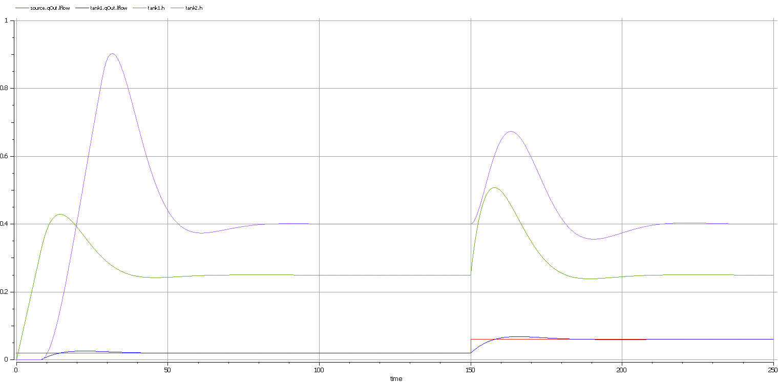
Here are the analyses of the result:
- The liquid flow increases sharply at time=150, to 0.06 m3/s, a factor of three of the previous flow level (0.02 m3/s)
- Tank1 regulated at height 0.25 and tank2 regulated at height 0.4 as expected (we set the parameter value through the data set)
- Both tank1 and tank2 regulated twice during the simulation; the first time regulated with the flow level 0.02 m3/s; the second time regulated with the flow level 0.06 m3/s
- Tank2 was empty before flow came out from tank1
Simulation and Analysis 2
We have set the tank's properties 'minV' and 'maxV' to values 0 and 10, respectively, in the example.
In the real world, a flow speed of 10 m3/s would require a very big valve to be installed on the tank.
What would happen if we changed the value of 'maxV' to 0.05 m3/s ?
Based on the previous model, we might make these changes:
- On the existing 'DataSet_1' of TanksConnectedPI, right-click and select 'Duplicate DataSet', and re-name to 'Tank2WithLimitValveSize'
- Click on the button to configure, expand 'tank2' and type '0.05' in the 'Value' column for the property 'maxV'
- Select 'Tank2WithLimitValveSize' on the 'Simulation' page and plot for the properties
- Click on the to execute the simulation
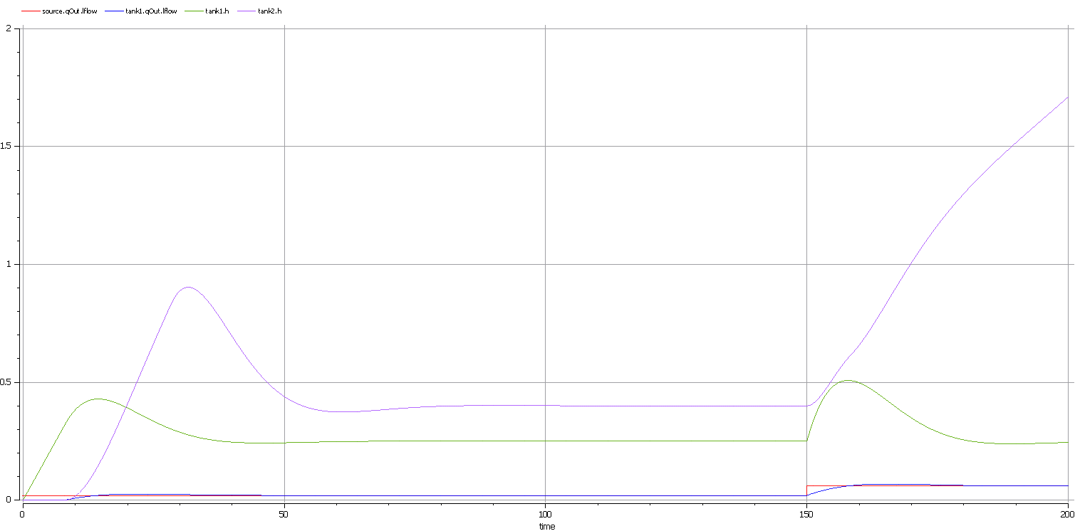
Here are the analyses of the result:
- Our change only applies to tank2; tank1 can regulate as before on 0.02 m3/s and 0.06 m3/s
- When the source flow is 0.02 m3/s, tank2 can regulate as before
- However, when the source flow increases to 0.06 m3/s, the valve is too small to let the out flow match the in flow; the only result is that the water level of tank2 increases
- It is then up to the user to fix this problem; for example, change to a larger valve, reduce the source flow or make an extra valve
In summary, this example shows how to tune the parameter values by duplicating an existing DataSet.

