| Prev | Next |
Configure SysML Simulation Window
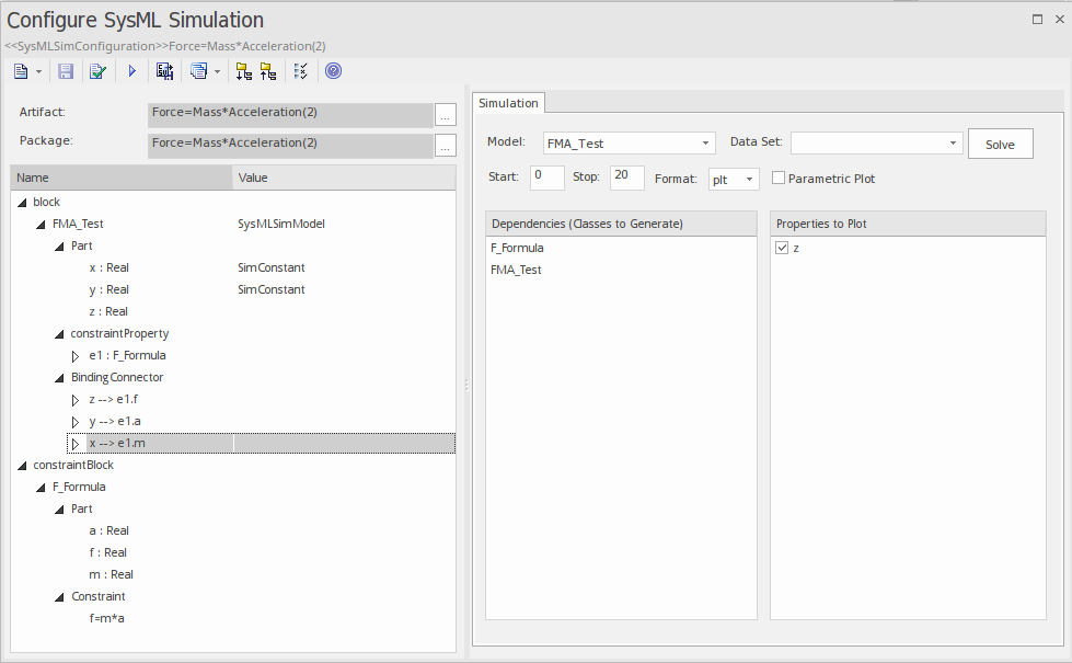
The Configure SysML Simulation window is the interface through which you can provide run-time parameters for executing the simulation of a SysML model. The simulation is based on a simulation configuration defined in a SysMLSimConfiguration Artifact element.
Access
|
Ribbon |
Simulate > System Behavior > Modelica > SysMLSim Configuration Manager |
|
Other |
Double-click on an Artifact with the SysMLSimConfiguration stereotype. |
Toolbar Options
Option |
Description |
See also |
|---|---|---|

|
Click on the drop-down arrow and select from these options:
|
|

|
Click on this button to save the configuration to the current Artifact. |
|

|
Click on this button to generate, compile and run the current configuration, and display the results. |
|

|
After simulation, the result file is generated in either plt, mat or csv format. That is, with the filename:
Click on this button to specify a directory into which Enterprise Architect will copy the result file. |
|

|
Click on this button to select from these options:
|
Simulation Artifact and Model Selection
Field |
Action |
See also |
|---|---|---|
|
Artifact |
Click on the |
Select |
|
Package |
If you have specified an existing SysMLSimConfiguration Artifact, this field defaults to the Package containing the SysML model associated with that Artifact. Otherwise, click on the |
Package Objects
This table discusses the types of object from the SysML model that will be listed under the 'Name' column in the Configure SysML Simulation window, to be processed in the simulation. Each object type expands to list the named objects of that type, and the properties of each object that require configuration in the 'Value' column.
Many levels of the object types, names and properties do not require configuration, so the corresponding 'Value' field does not accept input. Where input is appropriate and accepted, a drop-down arrow displays at the right end of the field; when you click on this a short list of possible values displays for selection. Certain values (such as 'SimVariable' for a Part) add further layers of parameters and properties, where you click on the  button to, again, select and set values for the parameters. For datasets, the input dialog allows you to type in or import values, such as initial or default values; see the Model Analysis using Datasets topic.
Element Type |
Behavior |
See also |
|---|---|---|
|
ValueType |
ValueType elements either generalize from a primitive type or are substituted by SysMLSimReal for simulation. |
|
|
Block |
Block elements mapped to SysMLSimClass or SysMLSimModel elements support the creation of data sets. If you have defined multiple data sets in a SysMLSimClass (which can be generalized), you must identify one of them as the default (using the context menu option 'Set as Default Dataset'). As a SysMLSimModel is a possible top level element for a simulation, and will not be generalized, if you have defined multiple datasets the dataset to use is chosen during the simulation. |
|
|
Properties |
Properties within a Block can be configured to be either SimConstants or SimVariables. For a SimVariable, you configure these attributes:
|
|
|
Port |
No configuration required. |
|
|
SimFunction |
Functions are created as operations in Blocks or Constraint Blocks, stereotyped as 'SimFunction'. No configuration is required in the Configure SysML Simulation window. |
|
|
Generalization |
No configuration required. |
|
|
Binding Connector |
Binds a property to a parameter of a constraint property. No configuration required. |
|
|
Connector |
Connects two Ports. No configuration required in the Configure SysML Simulation view. However, you might have to configure the properties of the Port's type by determining whether the attribute isConserved should be set as 'False' (for potential properties, so that equality coupling is established) or 'True' (for flow/conserved properties, so that sum-to-zero coupling is established). |
|
|
Constraint Block |
No configuration required. |
Simulation Tab
This table describes the fields of the 'Simulation' tab on the Configure SysML Simulation view.
Field |
Action |
See also |
|---|---|---|
|
Model |
Click on the drop-down arrow and select the top level node (a SysMLSimModel element) for the simulation. The list is populated with the names of the Blocks defined as top-level, model nodes. |
Creating a Parametric Model |
|
Data Set |
Click on the drop-down arrow and select the dataset for the selected model. |
Model Analysis using Datasets |
|
Start |
Type in the initial wait time before which the simulation is started, in seconds (default value is 0). |
|
|
Stop |
Type in the number of seconds for which the simulation will execute. |
|
|
Format |
Click on the drop-down arrow and select either 'plt', 'csv' or 'mat' as the format of the result file, which could potentially be used by other tools. |
|
|
Parametric Plot |
Note: With the checkbox selected, you must select two properties to plot. |
|
|
Dependencies |
Lists the types that must be generated to simulate this model. |
|
|
Properties to Plot |
Provides a list of variable properties that are involved with the simulation. Select the checkbox against each property to plot. |

