| Prev | Next |
Entering a State
The semantics of entering a State depend on the type of State and the manner in which it is entered.
In all cases, the entry Behavior of the State is executed (if defined) upon entry, but only after any effect Behavior associated with the incoming Transition is completed. Also, if a doActivity Behavior is defined for the State, this Behavior commences execution immediately after the entry Behavior is executed.
For a Composite State with one or more Regions defined, a number of alternatives exist for each Region:
- Default entry: This situation occurs when the owning Composite State is the direct target of a Transition; after executing the entry Behavior and forking a possible doActivity Behavior execution, State entry continues from an initial Pseudostate via its outgoing Transition (known as the default Transition of the State) if it is defined in the Region
If no initial Pseudostate is defined, this Region will not be active - Explicit entry: If the incoming Transition or its continuations terminate on a directly contained substate of the owning composite State, then that substate becomes active and its entry Behavior is executed after the execution of the entry Behavior of the containing composite State
This rule applies recursively if the Transition terminates on an indirect (deeply nested) substate - Shallow history entry: If the incoming Transition terminates on a shallowHistory Pseudostate of this Region, the active substate becomes the substate that was most recently active (except FinalState) prior to this entry, unless this is the first entry into this State; if it is the first entry into this State or the previous entry had reached a final, a default shallow history Transition will be taken if it is defined, otherwise the default State entry is applied
- Deep history entry: The rule for this case is the same as for shallow history except that the target Pseudostate is of type deepHistory and the rule is applied recursively to all levels in the active State configuration below this one
- Entry point entry: If a Transition enters the owning composite State through an entryPoint Pseudostate, then the outgoing Transition originating from the entry point and penetrating into the State in this region is taken; if there are more outgoing Transitions from the entry points, each Transition must target a different Region and all Regions are activated concurrently
For orthogonal States with multiple Regions, if the Transition explicitly enters one or more Regions (in the case of a Fork or entry point), these Regions are entered explicitly and the others by default.
In this example, we demonstrate a model with all these entry behaviors for an orthogonal State.
Modeling a StateMachine
Context of StateMachine
- Create a Class element named MyClass, which serves as the context of the StateMachine.
- Right-click on MyClass in the Project Browser and select the 'Add | StateMachine' option.
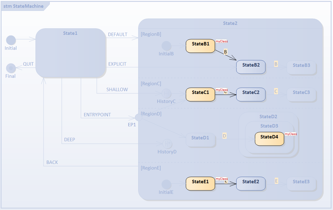
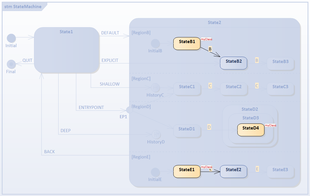
StateMachine
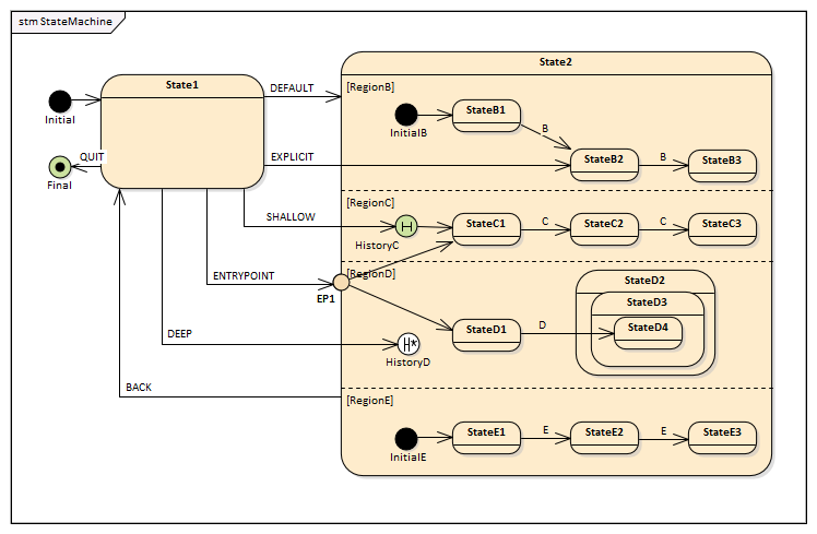
- Add to the diagram an Initial Node, a State named State1, a State named State2, and a Final element named final.
- Enlarge State2 on the diagram, right-click on it and select the 'Advanced | Define Concurrent Substates' option, and define RegionB, RegionC, RegionD and RegionE.
- Right-click on State2 and select the 'New Child Element | Entry Point' option to create the Entry Point EP1.
- In RegionB, create the elements InitialB, transition to StateB1, transition to StateB2, transition to StateB3; all transitions triggered by Event B.
- In RegionC, create the elements shallow HistoryC (right-click on History node | Advanced | Deep History | uncheck), transition to StateC1, transition to StateC2, transition to StateC3; all transitions triggered by Event C.
- In RegionD, create the elements deep HistoryD (right-click on History node | Advanced | Deep History | check), transition to StateD1, create StateD2 as parent of StateD3, which is parent of StateD4; transition from StateD1 to StateD4; triggered by Event D.
- In RegionE, create the elements InitialE, transition to StateE1, transition to StateE2, transition to StateE3; all transitions triggered by Event E.
- Draw transitions from the Entry Point EP1 to StateC1 and StateD1.
Draw transitions for different entry types:
- Default Entry: State1 to State2; triggered by Event DEFAULT.
- Explicit Entry: State1 to StateB2; triggered by Event EXPLICIT.
- Shallow History Entry: State1 to HistoryC; triggered by Event SHALLOW.
- Deep History Entry: State1 to HistoryD; triggered by Event DEEP.
- Entry Point Entry: State1 to EP1; triggered by Event ENTRYPOINT.
Other Transitions:
- Composite State Exit: from State2 to State1; triggered by Event BACK.
- State1 to Final, triggered by Event QUIT.
Simulation
Artifact
Enterprise Architect supports C, C++, C#, Java and JavaScript. We use JavaScript in this example because we don't need to install a compiler. (For other languages, either Visual Studio or JDK are required.)
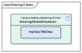
- On the 'Artifacts' page of the Diagram Toolbox, drag the Executable StateMachine icon onto a diagram and create an Artifact named EnteringAStateSimulation. Set the language to JavaScript.
- the MyClass element from the Project Browser onto the EnteringAStateSimulation Artifact, select the 'Paste as Property' option and give the Property the name myClass.
Code Generation
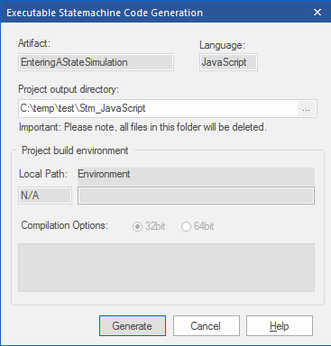
- Click on EnteringAStateSimulation and select the 'Simulate > Executable > StateMachines > Generate, build and run' ribbon option.
- Specify a directory for the generated source code.
Note: The contents of this directory will be cleared before generation; make sure you specify a directory that is used only for StateMachine simulation purposes.
Run Simulation
Tips: You can view the execution trace sequence from the Simulation window, which you open by selecting the 'Simulate > Simulator > Open Simulation Window' ribbon option
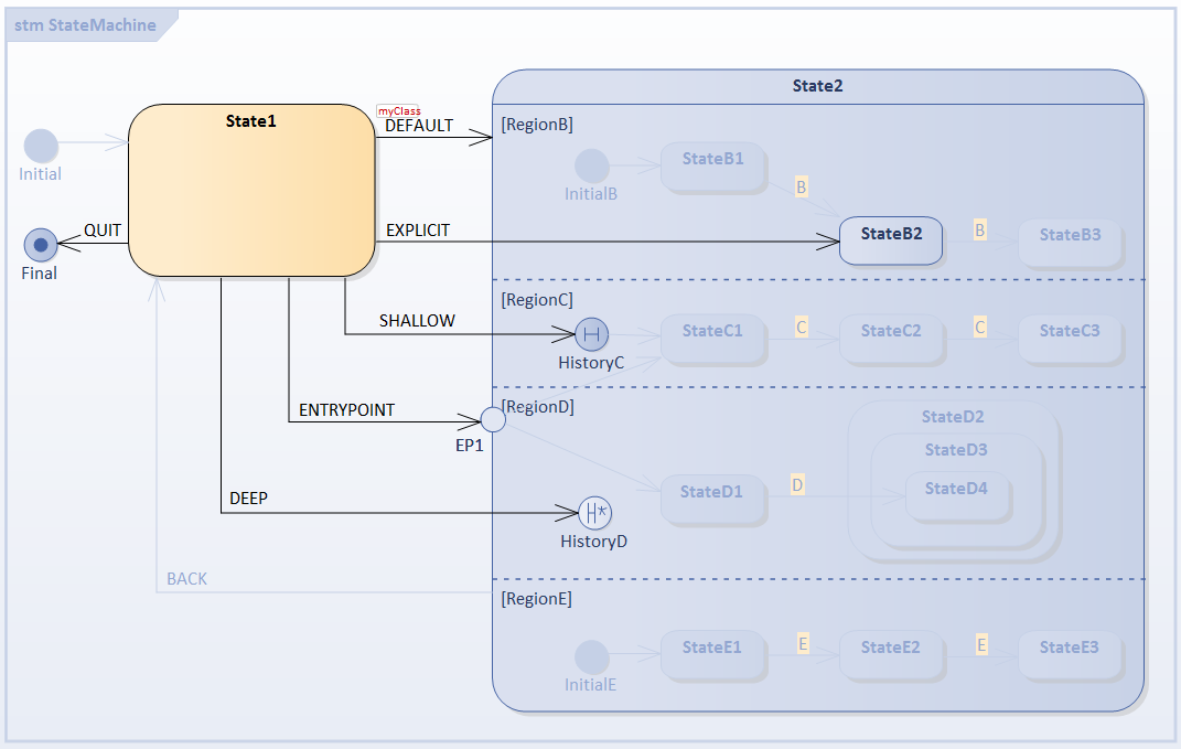
When the simulation begins, State1 is active and the StateMachine is waiting for events.
Open the Simulation Events (Triggers) window using the 'Simulate > Dynamic Simulation > Triggers' ribbon option.
1) Select the Default Entry: Trigger Sequence [DEFAULT]
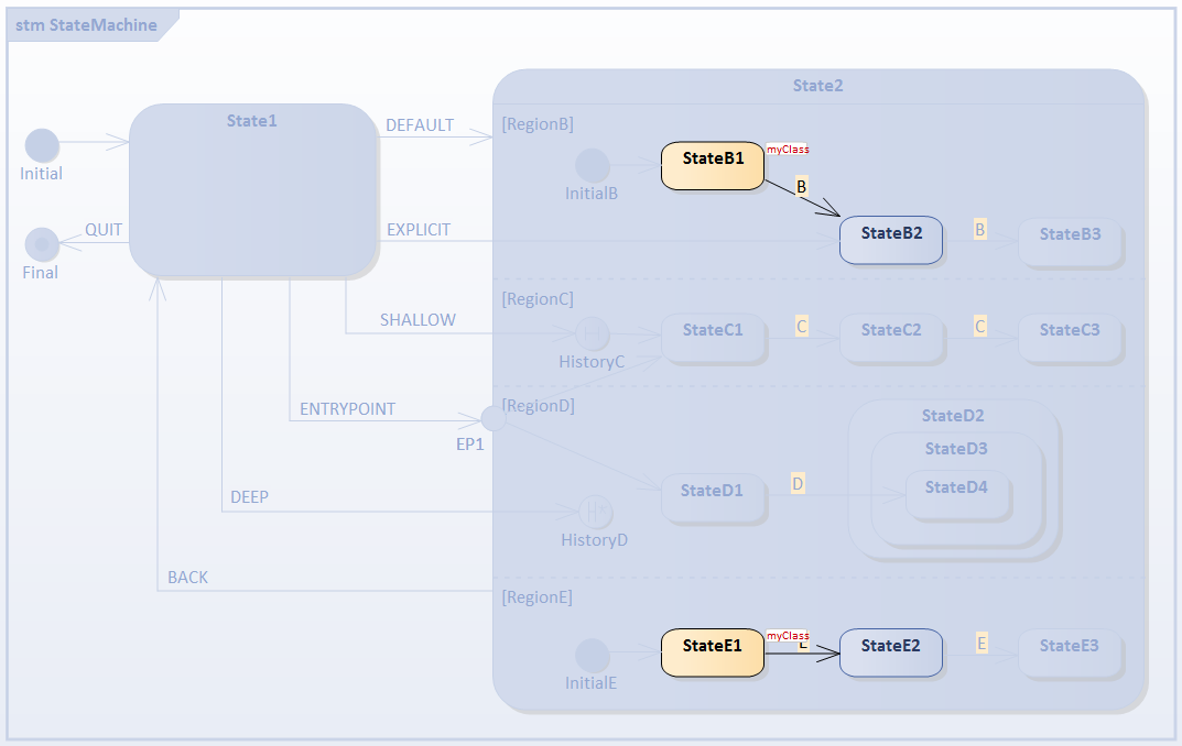
- RegionB is activated because it defines InitialB; the transition outgoing from it will be executed, StateB1 is the active state
- RegionE is activated because it defines InitialE; the transition outgoing from it will be executed, StateE1 is the active state
- RegionC and RegionD are inactive because no Initial Pseudostates were defined
Select the Trigger [BACK] to reset.
2) Select the Explicit Entry: Trigger Sequence [EXPLICIT]
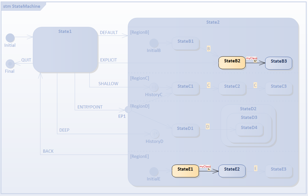
- RegionB is activated because the transition targets the contained vertex StateB2
- RegionE is activated because it defines InitialE; the transition outgoing from it will be executed, StateE1 is the active state
- RegionC and RegionD are inactive because no Initial Pseudostates were defined
Select the Trigger [BACK] to reset.
3) Select the Default History Transition: Trigger Sequence [SHALLOW]
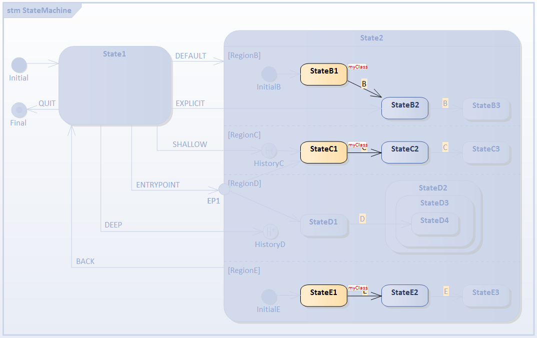
- RegionC is activated because the transition targets the contained vertex HistoryC; since this region is entered for the first time (and the History pseudostate has nothing to 'remember'), the transition outgoing from HistoryC to StateC1 is executed
- RegionB is activated because it defines InitialB; the transition outgoing from it will be executed, StateB1 is the active state
- RegionE is activated because it defines InitialE; the transition outgoing from it will be executed, StateE1 is the active state
- RegionD is inactive because no Initial Pseudostate was defined
4) Prepare for testing Shallow History Entry: Trigger Sequence [C, C]
- We assume shallow history pseudostate HistoryC can remember StateC3
Select the Trigger [BACK] to reset.
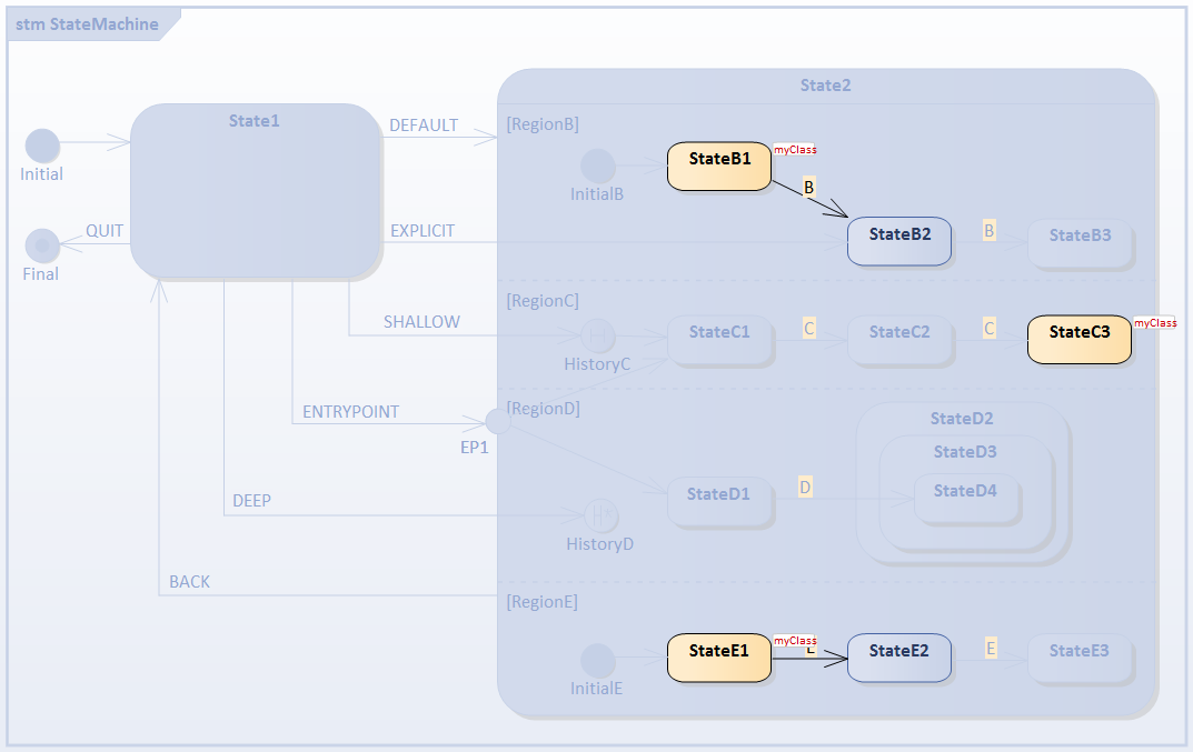
5) Select the Shallow History Entry: Trigger Sequence [SHALLOW]
- For RegionC, StateC3 is activated directly
Select the Trigger [BACK] to reset.
6) Select the Entry Point Entry: Trigger Sequence [ENTRYPOINT]

- RegionC is activated because the transition from EP1 targets the contained StateC1
- RegionD is activated because the transition from EP1 targets the contained StateD1
- RegionB is activated because it defines InitialB; the transition outgoing from it will be executed, StateB1 is the active state
- RegionE is activated because it defines InitialE; the transition outgoing from it will be executed, StateE1 is the active state
7) Prepare for testing Deep History: Trigger Sequence [D]
- We assume deep history pseudostate HistoryD can remember StateD2, StateD3 and StateD4
Select the Trigger [BACK] to reset.
8) Select the Deep History Entry: Trigger Sequence [DEEP]
- For RegionD, StateD2, StateD3 and StateD4 are entered; the traces are:
- myClass[MyClass].StateMachine_State1 EXIT
- myClass[MyClass].State1__TO__HistoryD_105793_61752 Effect
- myClass[MyClass].StateMachine_State2 ENTRY
- myClass[MyClass].StateMachine_State2 DO
- myClass[MyClass].InitialE_105787__TO__StateE1_61746 Effect
- myClass[MyClass].StateMachine_State2_StateE1 ENTRY
- myClass[MyClass].StateMachine_State2_StateE1 DO
- myClass[MyClass].InitialB_105785__TO__StateB1_61753 Effect
- myClass[MyClass].StateMachine_State2_StateB1 ENTRY
- myClass[MyClass].StateMachine_State2_StateB1 DO
- myClass[MyClass].StateMachine_State2_StateD2 ENTRY
- myClass[MyClass].StateMachine_State2_StateD2_StateD3 ENTRY
- myClass[MyClass].StateMachine_State2_StateD2_StateD3_StateD4 ENTRY

