| Prev | Next |
UPDM Framework Diagram
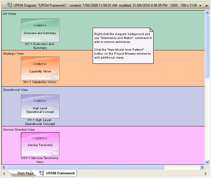
When developing and distributing a model, it is useful to have a single front page diagram that has hyperlinks to all the important information in the model. That is the aim of the UPDM Framework diagram, which is created with color-coded swimlanes for each set of views. You can drag and drop Packages (which act as hyperlinks to the documents that they own), Document Artifacts, any kind of composite element that points to its child diagram, or Hyperlinks pointing to custom SQL queries, Relationship Matrix profiles or external files.
Create a UPDM Framework Diagram
Editing Swimlanes
You can add, remove and modify the swimlanes on the Framework diagram. Select 'Design > Diagram > Edit > Swimlanes'.
To change the width of swimlanes, use the mouse to drag their boundaries.
Changing Appearances
Each Package, document and hyperlink on the Framework diagram has an alternative image. To load these images into your model, select 'Specialize > Technologies > UPDM > Import UPDM Images'.
If you want to apply your own bitmap images to the UPDM elements, you must first import the images into the model using the 'Configure > Reference Data > Images' option. Then you can either select the element and press to add an alternate image to the element, or you can apply your own stereotype to apply a Shape Script to the element. For example, you might define a stereotype with this Shape Script:
shape main
{
v_align="center";
h_align="center";
defSize(90,70);
image("myBitMap.bmp",0,0,100,100);
printWrapped("#name#");
}
Learn more

