| Prev | Next |
Setting ArcGIS Coordinate Systems
ArcGIS Feature Classes and Feature Datasets use spatial references, which consist of a coordinate system and associated values such as XY resolution and various tolerance values.
You can capture spatial reference properties using a Class stereotyped as «SpatialReference», which is available from the ArcGIS Toolbox pages. The ArcGIS model Pattern includes a Package named Spatial References, as a placeholder for creating such elements.
To help you model spatial reference properties, Enterprise Architect provides a dialog for selecting one of the predefined coordinate systems supported by ArcGIS. When you select a Geographic or Projected coordinate system, Enterprise Architect automatically inserts default values for the associated properties, such as Well Known Text (WKT), resolution, precision or tolerances. These values are held as Tagged Values on the «SpatialReference» element.
You can also add vertical coordinates to a selected Geographic or Projected coordinate system; the vertical coordinate is loaded to the VCSWKT and VCSWKID Tagged Values on the «SpatialReference» element.
This is an example «SpatialReference» element:
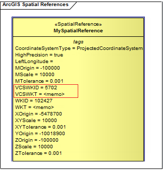
Looking at the WKT Tagged Value in the Tagged Values window for this element, you can see that the 'WGS 1984 Australian Centre for Remote Sensing Lambert Projected Coordinate' system has been selected.
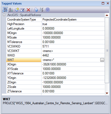
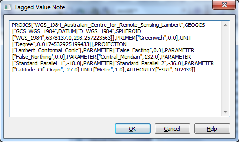
You can expand the information held in this Tagged Value by viewing its Tagged Value Note.
Define a Spatial Reference element
Step |
Action |
See also |
|---|---|---|
|
1 |
Open the diagram under the Spatial References Package of your ArcGIS model. (You can actually use any ArcGIS diagram in your model to define Spatial Reference elements; however, this diagram is a convenient placeholder created by Enterprise Architect's model Pattern for ArcGIS.) |
|
|
2 |
Drag a Spatial Reference element from the 'Workspace' page of the ArcGIS Core Toolbox onto the diagram. |
|
|
3 |
Right-click on the Spatial Reference element, and select the 'Extensions | ArcGIS | Set Coordinate System' menu option. The 'Set Coordinate System' dialog displays. |
|
|
4 |
Expand the Geographic or Projected Coordinate Systems hierarchy as appropriate and click on the required coordinate system in the list. |
|
|
5 |
If you want to also apply a vertical coordinate system, click on the The 'Set Vertical Coordinate System' dialog displays, containing a hierarchy that you again expand and from which you select a listed vertical coordinate system. Click on the to return to the 'Set Coordinate System' dialog; the 'Vertical Coordinate' field now displays the system you selected. |
|
|
6 |
Click on the to close the dialog and return to the diagram. The Tagged Values for the Spatial Reference element are updated with the Coordinate System information you have selected. |
 button at the right of the 'Vertical Coordinate' field.
 Notes

