| Prev | Next |
Create Diagram Profiles using the Profile Helpers
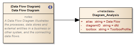
When you develop an MDG Technology, it is possible to create extended diagram types and include them in your MDG Technology as custom Diagram Profiles. For example, you might create a DFD Diagram Profile that defines a DFD diagram as an extension of the built-in Analysis diagram, as shown:
The Add Diagram Extension Profile Helper can assist you in defining your Diagram Profile, adding the necessary elements and giving them the appropriate attributes to define the functionality of the resulting Custom diagram types.
Create extended diagram types
Step |
Action |
See also |
|---|---|---|
|
1 |
If you have not done so already, use the Model Wizard's 'MDG Technology Builder' option to create a set of Packages for defining Profiles. In the Project Browser, locate the Package with the <<diagram profile>> stereotype and open its child diagram. |
Using the Profile Helpers |
|
2 |
Drag the 'Add Diagram Extension' item from the 'Profile Helpers' page of the Toolbox onto the diagram. The 'Add Diagram Extension' dialog displays. |
|
|
3 |
In the 'Name' field, type the name for the Custom diagram type. |
|
|
4 |
In the 'Extension Type' field click on the drop-down arrow and select the built-in diagram type that the Custom diagram type will extend. |
|
|
5 |
In the 'Description' field type a brief description of what the diagram is used for. When a user selects this diagram type in the 'New Diagram' dialog, this description will be displayed in the bottom right of the dialog. |
|
|
6 |
Within the 'Properties' pane enter values for these fields:
|
|
|
7 |
The remaining fields in the 'Properties' pane can be used to customize the diagram's default options. Any Attributes left blank will not be applied. When a user selects a field, a description of the property's effect is displayed at the bottom of the 'Properties' pane. |
|
|
8 |
Click on the . The appropriate Stereotype and Metaclass elements are added to the diagram. |
|
|
9 |
Repeat steps 2 to 8 for each diagram extension to include in the diagram Profile. |
|
|
10 |
Save the diagram as a Profile. |
Export a Profile |
|
11 |
Incorporate the Profile into an MDG Technology. |
Add a Diagram Profile Create MDG Technology File |
Notes
Learn more

