| Prev | Next |
Requirements Diagram
A Requirements diagram is one of Enterprise Architect's extended diagram types. It allows an analyst to model requirements visually, showing how requirements relate to each other and how they connect with other elements in the model such as Business Drivers, Constraints, Business Rules, Use Cases and design Components. The Requirement will be the main element seen on these diagrams; it has a name, a description and a series of properties (called attributes in some literature) such as status, complexity, difficulty and author. Enterprise Architect is designed to be a flexible tool and allows requirements to be created directly in the repository without the use of a diagram, but the diagram has proven to be a powerful tool to express the important role requirements play in the development process.
Example Diagram

Requirements Toolbox
You can create elements by dragging them from the 'Requirements' pages of the Diagram Toolbox onto the diagram canvas. Connectors can also be selected from the Toolbox and dragged between elements in the diagram or by using the Quick Linker. This table lists the elements available from the 'Requirements' toolbox but it is important to remember that other elements such as Use Cases and Components can be added to the diagram by opening other Toolbox pages - click on  to display the 'Find Toolbox Item' dialog and specify the element name.
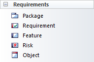
Requirements Toolbox Elements
Element |
Usage |
|---|---|
|
Package |
Packages are container elements that can be used to group requirements and other elements into sets. They are not requirements themselves but act as a grouping mechanism; analysts should take care that the Package is not a high level requirement. |
|
Requirement |
The Requirement element is used for modeling a condition or capability that a system must have. The type of the requirement can be set but there are also a number of types of requirements such as Functional, User and Architectural requirements available from the Extended Requirements page of the toolbox. They are useful for modeling a range of other entities such as Rationales and Assumptions. |
|
Feature |
A Feature is a characteristic or property that the system must have to meet its business requirements. They are typically high level properties that represent a group of requirements. |
|
Risk |
A Risk is a condition that could cause the disruption, loss or compromise of a system. The element can be used to model both technical and business risks and can be connected to one or more elements. |
|
Object |
Objects are useful for modeling any of the entities that are discussed during a requirements elicitation workshop or while reading through project documentation. Formally they are Instances of Classes and when analysis is conducted a Domain Class can be derived from one or more objects. |
Requirements Relationship Toolbox
You can create relationships by selecting the corresponding icon in the Toolbox and dragging between any two elements in the diagram canvas, or by using the Quick Linker. This table lists the relationships available from the 'Requirements Relationship' page of the Toolbox but it is important to remember that other relationships such as Composite can be added to the diagram by opening other Toolbox pages.
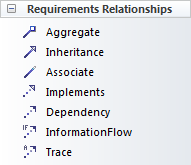
Requirements Relationships Toolbox
Connector |
Use |
|---|---|
|
Aggregate |
Used to show that a requirement (diamond end) is made up of a another requirement (tail end). This allows hierarchies of requirements to be created. |
|
Inheritance |
Used to show that an element (triangle end) is a more generalized version of another element (tail end). The relationship is used between Classifiers such as Use Cases, Classes, Artifacts and Components. |
|
Associate |
Used to show a semantic or structural relationship between two elements. |
|
Implements |
Used to show that a model element implements a Requirement. Typically it would be used by an architect or designer to indicate that the need expressed in the Requirement would be met by a particular module, Use Case or Component in the system. |
|
Dependency |
Used to show that a Requirement (tail end) relies upon another element (arrow end). |
|
Information Flow |
Used to show that data flows between two elements in a Repository. The type of data can be represented as Information Items that can be selected from any part of the model. They could be used to show the Requirement that information flows between the proposed system and a supplier's system or to represent a Constraint that two Components must communicate via a certain protocol. |
|
Trace |
Used to show that an element (tail end) is more elaborated in the model than the element at the arrow end. So a User Requirement could be traced to a Stakeholder Requirement or to a Business Goal, |
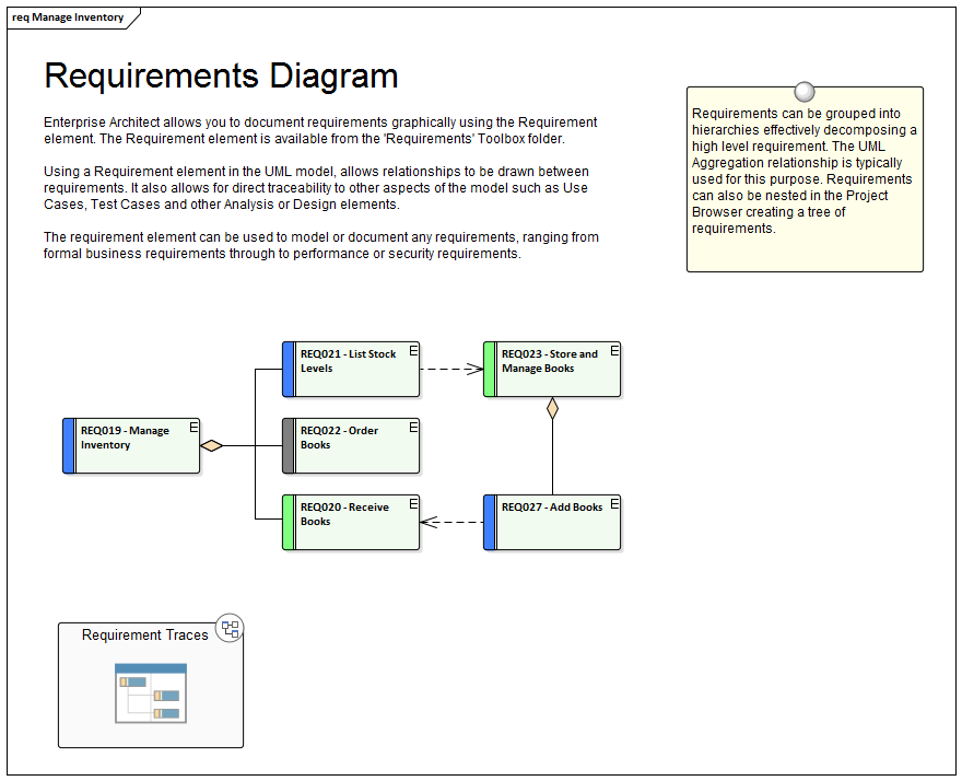
Example Diagram - Hierarchies
This diagram shows how requirements can be connected into hierarchies thus allowing high level requirements to be broken down to verifiable requirements.
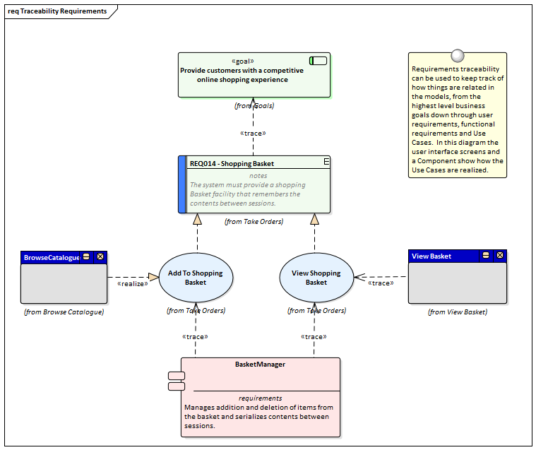
Example Diagram - Traces
This diagram shows how Requirements can be connected to other elements in the model thus displaying traceability.